Automatic multi-comb chain grates
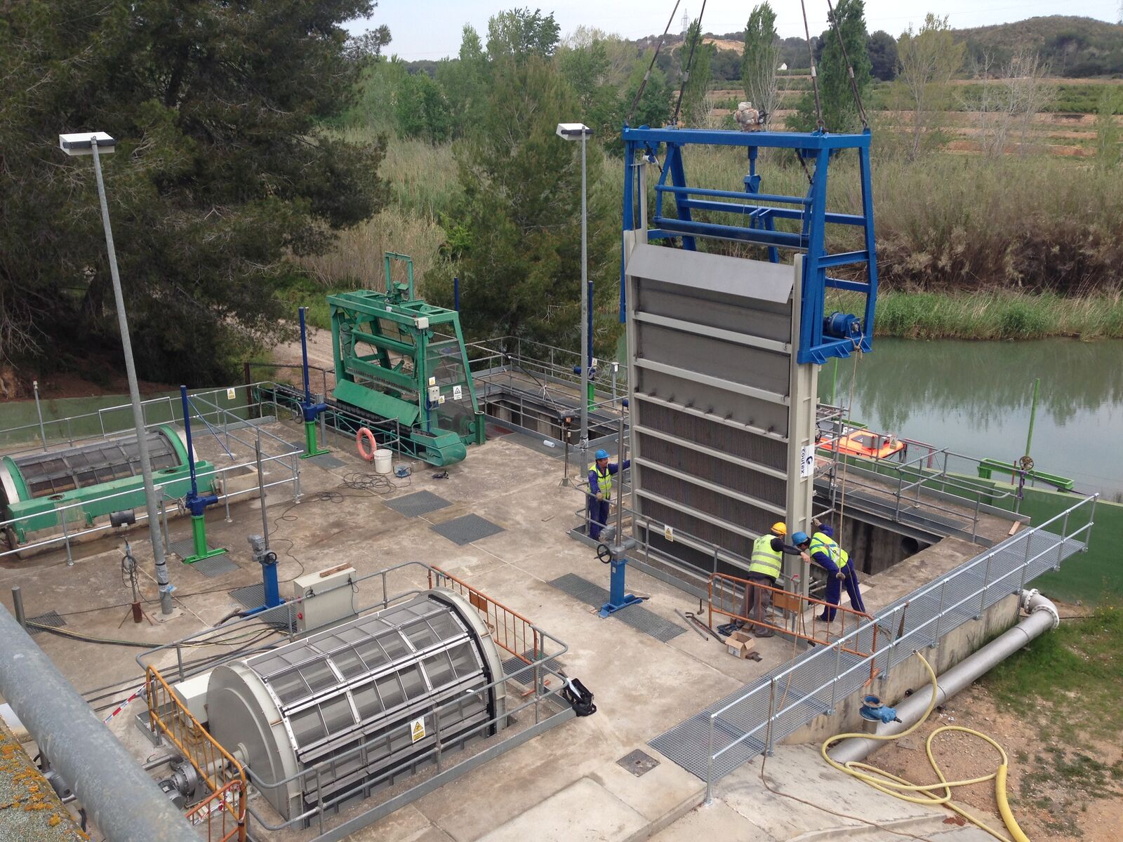
An automatic multi-comb chain grate can operate at significant depths and has a width of up to 2,500 mm.
This hydraulic equipment, featuring multiple combs connected to a drive chain, is crucial for sewage treatment plants, pumping stations and industrial facilities where raw water with suspended solids needs to be screened.
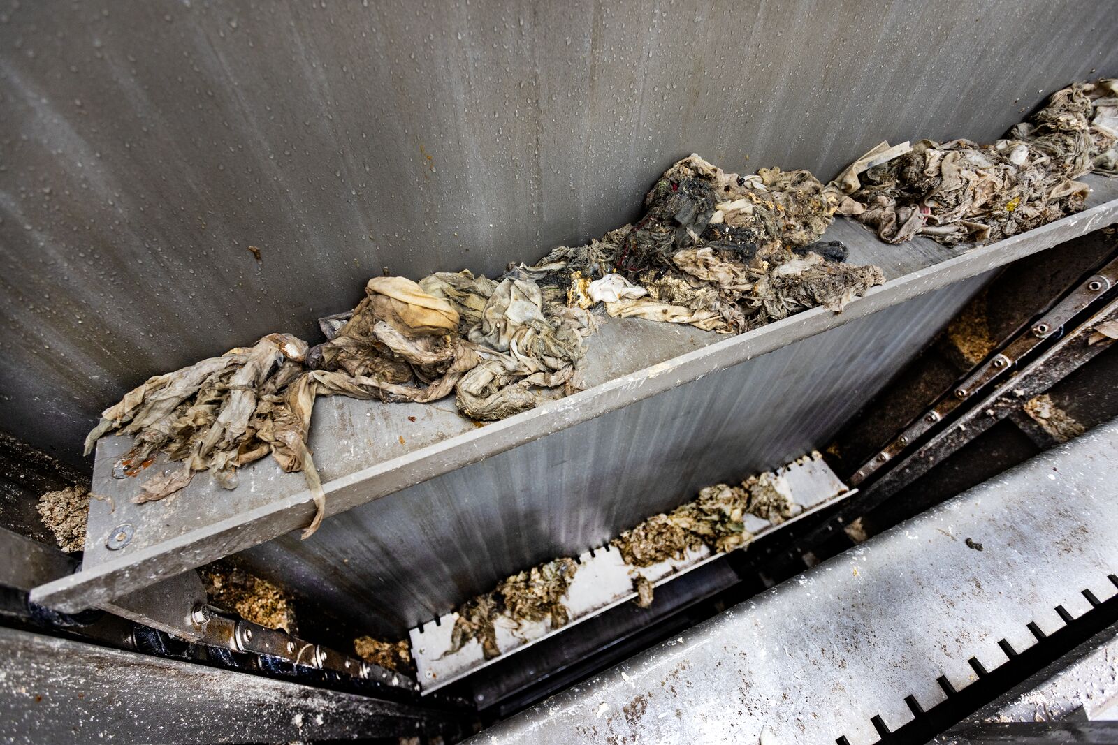
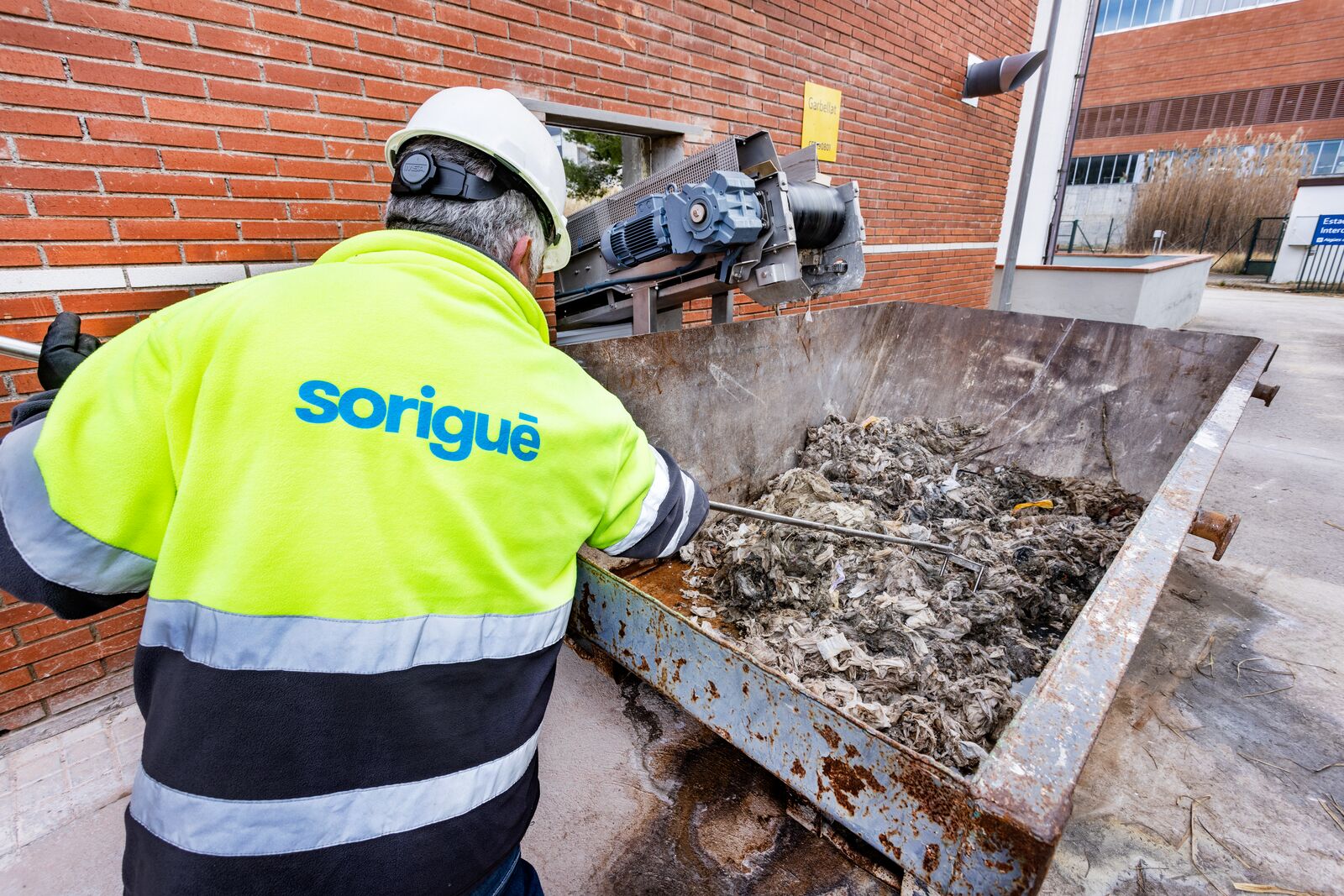
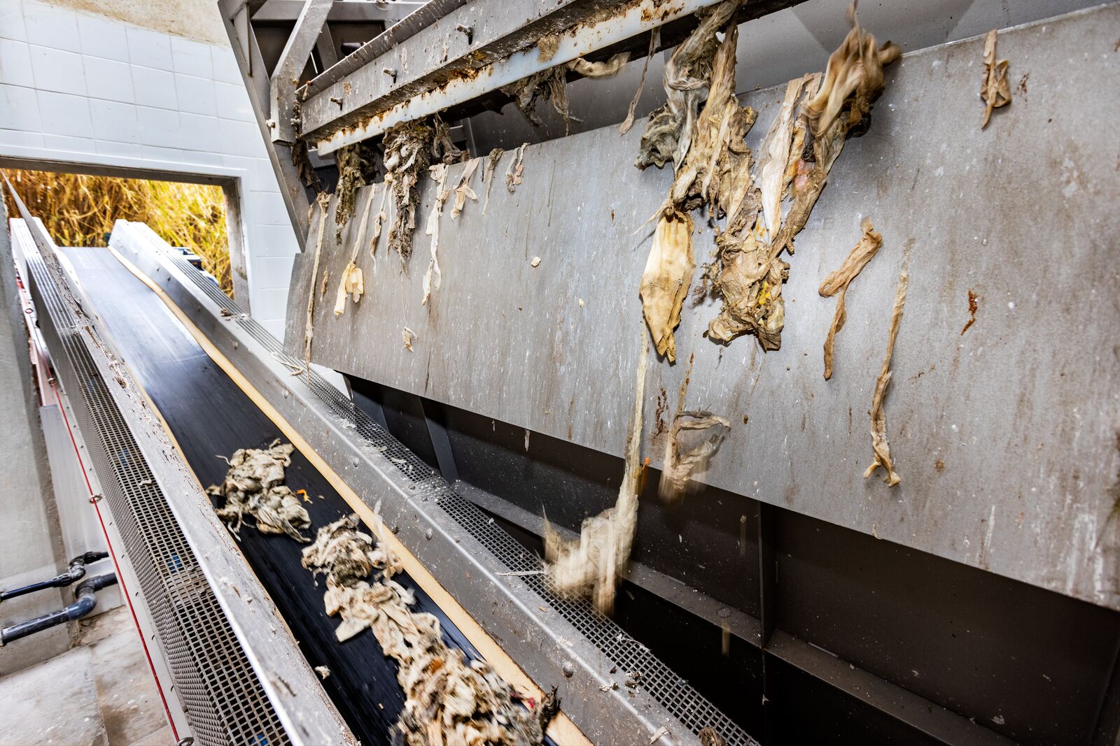
It efficiently removes a large amount of solids in a very short cleaning cycle. Coutex Sorigué meets the demanding needs of wastewater treatment plants with automatic multi-chain grates capable of separating the wipes that cause so much damage in these installations.
Components
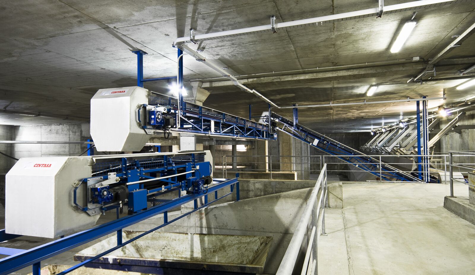
The main components of the grate are the drive unit, frame, grate and cleaning system.
Dimensions
The following data are required for calculating the dimensions of an automatic multi-comb grate:
- Width and height of the canal.
- Maximum water level from the base of the canal.
- Pitch.
- Waste type.
- Discharge height measured above the manoeuvring floor.
Technical data
Drive unit
The drive system features an electric geared motor mounted on the upper shaft, with two main sprockets that transmit movement to the system via a link chain.
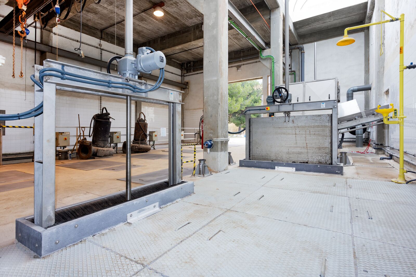
Frame
The frame is constructed from a tubular structure or folded sheet metal and welded sections, providing the robustness of a monoblock enclosure to ensure the equipment’s transport and installation.
Grate
The bars are arranged with spacing as needed, typically ranging from 8 to 100 mm, depending on installation requirements and the type of waste present. Designed and calculated to withstand 100% of the hydraulic thrust. The angle of inclination is typically 75º relative to the slab, although it can be designed for other angles. The bars have a rectangular geometry.
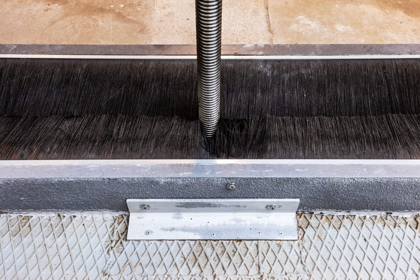
Cleaning system
The primary component of this grate is the combs connected to the drive chains. These combs can be installed in quantities ranging from two to an unlimited number, depending on the height of the grate and integration requirements. When the discharge height is reached, the combs are cleaned by a comb cleaner without the need for an electric drive. The tilting geometry itself facilitates the removal of residue contained in the comb.